


NX
Category:
Single row cylindrical roller bearings with cage
Chat with us now for a quick response.
Keyword:
NX
PRODUCT DETAILS
Technical characteristics
Single row cylindrical roller bearings with cage are radial and separable bearings.
Due to the possibility of fitting the different com - ponents of the bearings,i.e.the outer and the inner rings,individually,the mounting becomes easier.
In addition, this technical characteristics are allowed to be used in the inner and outer circles, which is an advantage in the application of vibration or impact load.
Their boundary dimensions are standardized by the DIN Standards,DIN Standard 616 plans and DIN 5412/part
Depending on their design,single row cylindrical roller bearings can be used as non-locating bea- rings,semi-locating bearings or as locating bea- rings
N and NU type cylindricalroller bearings are ideal non-locating bearings,other design variations,i.e. NJ,NF and NU+HJ designs,can also handle thrust forces up to an certain amount in one
direction, and others like NJ+HJ and NUP can admit loads acting in bothdirections.
Single row cylindrical roller bearings feature rela- tively high speed ratings when compared to other roller bearing types.
In the case of bearing applications having only li- mited space available (i.e.gear boxes),single row cylindrical roller bearings can also be used without theirrespective outer or inner rings,i.e.RN-
type and RNU-type bearings,respectively.
These bearing design types allow the rollers to run directly onto the contacting surface of either the shaft or in the housing.
However,in such bearing arrangements the con- tacting surface parts must be hardened and ground as for regular bearing raceways.
Standard design variants
VEO single row cylindrical roller bearings are avai- lable in several basic designs as standard.
The most important design variants are shown below (see Fig.1).
NU -type bearings feature an outer ring with two fixed lips (flanges)whilst the inner ring is plain.
N-design bearings have two fixed lips on the in- ner ring and a plain outer ring.
NU and N design cylindrical roller bearings allow for a compensation of length changes of the shaft due to thermal expansion within the bearing This makes them perfect floating (non -locating) bearings.These bearing designs,therefore,are not suitable to accommodate any thrust force.
NJ-type cylindrical roller bearings feature two fixed lips on their outer ring and one lip on the inner ring.Bearings of NF design have one fixed lip on their outer ring and two lips on the inner ring.This allow for accepting single direction ac- ting thrust forces what make them semi-locating bearing types
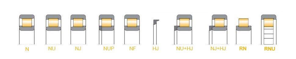
NUP cylindrical roller bearings are positioning bearing. The characteristics of this design variant are two fixed inner gears on its outer ring, and there is an overall gear and a gear on the inner
ring. NUP-type bearing can withstand a certain degree of thrust in any direction. They are positioning bearing.
HJ type thrust collars are being used in con- junction with cylindrical roller bearings for gui- ding shafts.
When used with HJ type thrust collars,semi lo- cating NJ-type cylindrical roller bearings can be turned into locating bearings,hence providing a guidance in both directions.
NU type cylindrical roller bearings should not be used with HJ thrust collars for preventing an erro- neously clamping of the rollers.NU type cylindri- cal roller bearings with a HJ thrust collar are
able to take upthrust forces acting in one direction only.Since these bearings are seldom used they have not been included in the data tables;plea- se,contactVEO sales department torequest
fur- ther information about these series.
Reinforced internal design,suffix E
VEO single row cylindrical roller bearings are pro- duced with the E design as standard up to a cer- tain size.
The E design incorporates an optimized internal design including more and larger rollers gaining increased load ratings and thus optimum perfor- mance.
However,for larger cylindrical roller bearingsand bearing types of the series 10 and 4,the NON-E design remains the standard.
In sameapplications,including repair and over-haul,the traditional NON-E-design remains.The-refore,the traditional NON-E-design can be pro-duced byVEO to customers order for all sizes.
Misalignment
Bearings running misaligned are subjected to additional forces resulting in reduced bearing life and also may generate high running noise,vibra- tions and excessive operating temperatures
VEO single row cylindrical roller bearings feature optimized internal contact geometry to minimize the negative effect of edge loading stresses bet- ween the rollers and the contacting races.
This optimized internal contact geometry inclu- des rollers having a modified outer profile inclu- ding an optimized i.e.so crowned raceway geo- metry
For normal operating conditions,the maximum misalignment between inner and outer ring must not exceed 2 angular minutes.
In cases where higher misalignments may occur VEO also supplies cylindrical roller bearings with special profile on the inner ring raceway to cus- tomer orders (suffix-PE).
Tolerances
VEO single row cylindrical roller bearings are pro- duced to tolerance class PN asstandard.
VEO bearings are also produced to closer toleran- ces to customers order.
For obtaining detailed values on tolerances refer to the chapter Bearing data and Tolerances
Cages
VEOE Type cylindrical roller bearings are normally fitted with glass fiber reinforced polyamide cages (suffix -TVP2)as standard.Bigger sizes are mainly fitted with a two-piece machine brass cage
with integral rivets (suffixes -M1 as standard or -M2 as optional).
Non-E designVEO single row cylindrical roller bea- rings are normally fitted with pressed steel cages asstandard (suffix-J).
Exceptions are larger cylindrical roller bearings and bearings of the series 10 and 4 which are pro- duced with machined solid brass cages with steel rivets (suffix -M)as standard.
VEO cylindrical roller bearings are also available with other cage designs and cage materials on order request.
Internal radial clearance
VEO single row cylindrical roller bearings are stan- dard produced with normal internal clearance (group CN).
VEO cylindrical roller bearings can also produce to otherinternal clearance groups to order.
The clearance values correspond,as far as they are standardized,to the relevant international standards DIN 620 part 4 and ISO 5753-1991.
Values of the different internal clearance groups of single row VEO cylindrical roller bearings are listed in tables 1 and 2(page 213 and 214).
Non-standardized clearances
VEO cylindrical roller bearings can also produce with individually defined special internal clearan- ces to order
This includes the possibility of producing bearings with a clearance restricted to a part of the full clearance range only,i.e.C2L,C3M,etc.
In case of internal clearance group C1,individual components are not interchangeable and must not be mixed to maintain the correct operating clearance.
Operating temperature
Single row cylindrical roller bearings with cage can be used at operating temperatures from -30℃ to +150°℃.In case of continuous operating temperatures above 120°℃,please contact VEO
application engineering department.
Bearings with a plasticcage (suffix-TVP2)are sui- tableup to +120°℃ .
Minimum load
Rolling bearings require a sufficient minimum radial load to prevent excessive sliding friction. Particularly cylindrical roller bearings require a minimum radial load of more than 4%of the dy-
namic load rating Cr.
Dynamic axial load carrying capacity
Cylindrical roller bearings are primarily designed to accommodate radial loads.Several designs are also suitable to accept thrust forces acting in one or both directions to a limited extend.
VEO single -column cylindrical roller bearings with cylindrical holes
|
Clearance group |
Bore diameter(mm) |
||||||||||||||
|
|
|
24 |
30 |
40 |
50 |
65 |
80 |
100 |
120 |
140 |
160 |
180 |
200 |
225 |
|
|
≤ |
24 |
30 |
40 |
50 |
65 |
80 |
100 |
120 |
140 |
160 |
180 |
200 |
225 |
250 |
|
|
C1 |
min |
5 |
5 |
5 |
5 |
5 |
10 |
10 |
10 |
10 |
10 |
10 |
15 |
15 |
15 |
|
max |
15 |
15 |
15 |
18 |
20 |
25 |
30 |
30 |
35 |
35 |
40 |
45 |
50 |
50 |
|
|
C2 |
min |
0 |
0 |
5 |
5 |
10 |
10 |
15 |
15 |
15 |
20 |
25 |
35 |
45 |
45 |
|
max |
25 |
25 |
30 |
35 |
40 |
45 |
50 |
55 |
60 |
70 |
75 |
90 |
105 |
110 |
|
|
CN |
min |
20 |
20 |
25 |
30 |
40 |
40 |
50 |
50 |
60 |
70 |
75 |
90 |
105 |
110 |
|
max |
45 |
45 |
50 |
60 |
70 |
75 |
85 |
90 |
105 |
120 |
125 |
145 |
165 |
175 |
|
|
C3 |
min |
35 |
35 |
45 |
50 |
60 |
65 |
75 |
85 |
100 |
115 |
120 |
140 |
160 |
170 |
|
max |
60 |
|
70 |
|
90 |
100 |
110 |
125 |
145 |
165 |
170 |
195 |
220 |
235 |
|
|
C4 |
min |
50 |
50 |
60 |
70 |
80 |
90 |
105 |
125 |
145 |
165 |
170 |
195 |
220 |
235 |
|
max |
75 |
75 |
85 |
100 |
110 |
125 |
140 |
165 |
190 |
215 |
220 |
250 |
280 |
300 |
|
|
C5 |
min |
65 |
70 |
80 |
95 |
110 |
130 |
155 |
180 |
200 |
225 |
250 |
275 |
305 |
330 |
|
max |
90 |
95 |
105 |
125 |
140 |
165 |
190 |
220 |
245 |
275 |
300 |
330 |
365 |
395 |
|
|
Clearance group |
Bore diameter(mm) |
||||||||||||||
|
|
250 |
280 |
315 |
355 |
400 |
450 |
500 |
560 |
630 |
710 |
800 |
900 |
1.000 |
1.120 |
|
|
≤ |
280 |
315 |
355 |
400 |
450 |
500 |
560 |
630 |
710 |
800 |
900 |
1.000 |
1.120 |
1.250 |
|
|
C1 |
min |
20 |
20 |
20 |
25 |
25 |
25 |
25 |
30 |
30 |
35 |
35 |
35 |
50 |
230 |
|
max |
55 |
60 |
65 |
75 |
85 |
95 |
100 |
110 |
130 |
140 |
160 |
180 |
200 |
470 |
|
|
C2 |
min |
55 |
55 |
65 |
100 |
110 |
110 |
120 |
140 |
145 |
150 |
180 |
200 |
220 |
230 |
|
max |
125 |
130 |
145 |
190 |
210 |
220 |
240 |
260 |
285 |
310 |
350 |
390 |
430 |
470 |
|
|
CN |
min |
125 |
130 |
145 |
190 |
210 |
220 |
240 |
260 |
285 |
310 |
350 |
390 |
430 |
470 |
|
max |
195 |
205 |
225 |
280 |
310 |
330 |
360 |
380 |
425 |
470 |
520 |
580 |
640 |
710 |
|
|
C3 |
min |
190 |
200 |
225 |
280 |
310 |
330 |
360 |
380 |
425 |
470 |
520 |
580 |
640 |
710 |
|
max |
260 |
275 |
305 |
370 |
410 |
440 |
480 |
500 |
565 |
630 |
690 |
770 |
850 |
950 |
|
|
C4 |
min |
260 |
275 |
305 |
370 |
410 |
440 |
480 |
500 |
565 |
630 |
690 |
770 |
850 |
950 |
|
max |
330 |
350 |
385 |
460 |
510 |
550 |
600 |
620 |
705 |
790 |
860 |
960 |
1.060 |
1.190 |
|
|
C5 |
min |
370 |
410 |
455 |
510 |
565 |
625 |
690 |
780 |
865 |
975 |
1095 |
|
|
|
|
max |
440 |
485 |
535 |
600 |
665 |
735 |
810 |
900 |
1005 |
1135 |
1265 |
|
|
|
|
VEO single -column cylindrical roller bearings with cone holes
|
Clearance group |
Bore diameter(mm) |
||||||||||||||
|
> |
|
24 |
30 |
40 |
50 |
65 |
80 |
100 |
120 |
140 |
160 |
180 |
200 |
225 |
|
|
≤ |
24 |
30 |
40 |
50 |
65 |
80 |
100 |
120 |
140 |
160 |
180 |
200 |
225 |
250 |
|
|
C1 |
min |
10 |
15 |
15 |
17 |
20 |
25 |
35 |
40 |
45 |
50 |
55 |
60 |
60 |
65 |
|
max |
20 |
25 |
25 |
30 |
35 |
40 |
55 |
60 |
70 |
75 |
85 |
90 |
95 |
100 |
|
|
C2 |
min |
15 |
20 |
20 |
25 |
30 |
35 |
40 |
50 |
55 |
60 |
75 |
85 |
95 |
105 |
|
max |
40 |
45 |
45 |
55 |
60 |
70 |
75 |
90 |
100 |
110 |
125 |
140 |
155 |
170 |
|
|
CN |
min |
30 |
35 |
40 |
45 |
50 |
60 |
70 |
90 |
100 |
110 |
125 |
140 |
155 |
170 |
|
max |
55 |
60 |
65 |
75 |
80 |
95 |
105 |
130 |
145 |
160 |
175 |
195 |
215 |
235 |
|
|
C3 |
min |
40 |
45 |
55 |
60 |
70 |
85 |
95 |
115 |
130 |
145 |
160 |
180 |
200 |
220 |
|
max |
65 |
70 |
80 |
90 |
100 |
120 |
130 |
155 |
175 |
195 |
210 |
235 |
260 |
285 |
|
|
C4 |
min |
50 |
55 |
70 |
75 |
90 |
110 |
120 |
140 |
160 |
180 |
195 |
220 |
245 |
270 |
|
max |
75 |
80 |
95 |
105 |
120 |
145 |
155 |
180 |
205 |
230 |
245 |
275 |
305 |
335 |
|
|
C5 |
min |
75 |
80 |
95 |
105 |
120 |
145 |
155 |
180 |
205 |
230 |
245 |
275 |
305 |
335 |
|
max |
100 |
105 |
120 |
135 |
150 |
180 |
190 |
220 |
250 |
280 |
295 |
330 |
365 |
400 |
|
|
Clearance group |
Bore diameter (mm) |
||||||||||||||
|
> |
250 |
280 |
315 |
355 |
400 |
450 |
500 |
560 |
630 |
710 |
800 |
900 |
1.000 |
1.120 |
|
|
|
280 |
315 |
355 |
400 |
450 |
500 |
560 |
630 |
710 |
800 |
900 |
1.000 |
1.120 |
1.250 |
|
|
C1 |
min |
75 |
80 |
90 |
100 |
110 |
120 |
130 |
140 |
160 |
170 |
190 |
210 |
230 |
|
|
max |
110 |
120 |
135 |
150 |
170 |
190 |
210 |
230 |
260 |
290 |
330 |
360 |
400 |
|
|
|
C2 |
min |
115 |
130 |
145 |
165 |
185 |
205 |
230 |
260 |
295 |
325 |
370 |
410 |
455 |
490 |
|
max |
185 |
205 |
225 |
255 |
285 |
315 |
350 |
380 |
435 |
485 |
540 |
600 |
665 |
730 |
|
|
CN |
min |
185 |
205 |
225 |
255 |
285 |
315 |
350 |
380 |
435 |
485 |
540 |
600 |
665 |
730 |
|
max |
255 |
280 |
305 |
345 |
385 |
425 |
470 |
500 |
575 |
645 |
710 |
790 |
875 |
970 |
|
|
C3 |
min |
240 |
265 |
290 |
330 |
370 |
410 |
455 |
500 |
565 |
630 |
700 |
780 |
865 |
960 |
|
max |
310 |
340 |
370 |
420 |
470 |
520 |
575 |
620 |
705 |
790 |
870 |
970 |
1075 |
1.200 |
|
|
C4 |
min |
295 |
325 |
355 |
405 |
455 |
505 |
560 |
620 |
695 |
775 |
860 |
960 |
1065 |
1.200 |
|
max |
365 |
400 |
435 |
495 |
555 |
615 |
680 |
740 |
835 |
935 |
1.030 |
1.150 |
1.275 |
1.440 |
|
|
C5 |
min |
365 |
400 |
435 |
495 |
555 |
615 |
680 |
740 |
835 |
935 |
1.030 |
1.150 |
1.275 |
|
|
max |
435 |
475 |
515 |
585 |
655 |
725 |
800 |
860 |
975 |
1.095 |
1.200 |
1.340 |
1.485 |
|
|
Thrust forces applied to cylindrical roller bea- rings generate sliding friction between the roller end faces and the guiding flanges.
Hence,an optimum lubrication is crucial.Fur- thermore,every thrust load creates a tilting mo- ment on the rollers.
This requires an additional radial loading to ensu- re an effective function of the bearing.
However,axially loaded cylindrical roller bea- rings also require:
·adequate lubrication
·no shock loads
·sufficient heat dissipation
·an adequate support of the bearing flanges by the adjacent parts
Design of bearing seats as raceways
In applications with limited space it may bead- vantageous using a cage and roller assembly with an outer or inner ring only in order to save on sectional height.
In these cases,the rollers run directly on the sur- faces of shaft or housing.These contacting surfa- ces must be hardened and ground as forbearing raceways
Typical types for these applications are RNU Se- ries or RN series
The contacting surface on shaft or housing acting as raceway must be produced to ISO tolerance field g6 and K6 respectively.
The diameters of the guiding flanges on shaft or housing must be in accordance with the respecti- ve shoulder diameters (d,or D₁),as given by the product tables.(NOTE:refer to the data of com-
plete bearings due to these types,RN and RNU are not detailed in the data table and if further information is required,consult us).
For detailed information on the design layout of raceways see chapter Design of bearing loca-tion.
Supplementary designations
The product tables show the standardized bea- ring configurations updated on the edition of this catalogue.These standardized configurations co- rrespond to suffix or suffixes of eachbearing.
In any case,VEO can offer,under requirement, alternative designs,comprising the ones showed in the following table or many others,whose mention exceeds the purpose of the present ca-
talogue,and can be found in specific technical publications of concrete applications or series of specific bearings.
Should you need a special design not existent in these pages,please contact our Sales Department in VEO Bearings Europe.
|
Suffix |
Description |
|
C2 |
Radial internal clearance smaller than normal |
|
C1 |
Radial internal clearance smaller than C2 |
|
C3 |
Radia internal clearance larger than normal |
|
C4 |
Radial internal clearance larger than C3 |
|
E |
Modified internal design to increase the load capacity |
|
TVP2 |
Glass fiber reinforced polyamide cage |
|
M |
Solid brass cage with steel rivets,roller guided |
|
MA |
Solid brass cage with steel rivets,outer ring guided |
|
MB |
Solid brass cage with steel rivets,inner ring guided |
|
M1 |
Solid brass cage with trapezoid integral brass rivets,hot riveted,roller guided |
|
M1A |
Solid brass cage with trapezoid integral brass rivets,hot riveted,outer ring guided |
|
M1B |
Solid brass cage with trapezoid integral brass rivets,hot riveted,inner ring guided |
|
M2 |
Solid brass cage with cylindrical integral brass rivets,hot riveted,roller guided |
|
M2A |
Solid brass cage with cylindrical integral brass rivets,hot riveted,outer ring guided |
|
M2B |
Solid brass cage with cylindrical integral brass rivets,hot riveted,inner ring guided |
|
MPA |
Singlepiece solid brass cage,outer ring guided |
|
MPB |
Single piece solid brass cage,inner ring guided |
|
J |
Pressedsteel cage |
|
PE |
Modified internal design to increase the misalignement capacity |
|
K |
Taperedbore,taper 1:12 |
|
CE01 |
Bearings for traction motorsof railway vehicles |
|
Suffix |
Description |
|
C2 |
Radial internal clearance smaller than normal |
|
C1 |
Radial internal clearance smaller than C2 |
|
C3 |
Radia internal clearance larger than normal |
|
C4 |
Radial internal clearance larger than C3 |
|
E |
Modified internal design to increase the load capacity |
|
TVP2 |
Glass fiber reinforced polyamide cage |
|
M |
Solid brass cage with steel rivets,roller guided |
|
MA |
Solid brass cage with steel rivets,outer ring guided |
|
MB |
Solid brass cage with steel rivets,inner ring guided |
|
M1 |
Solid brass cage with trapezoid integral brass rivets,hot riveted,roller guided |
|
M1A |
Solid brass cage with trapezoid integral brass rivets,hot riveted,outer ring guided |
|
M1B |
Solid brass cage with trapezoid integral brass rivets,hot riveted,inner ring guided |
|
M2 |
Solid brass cage with cylindrical integral brass rivets,hot riveted,roller guided |
|
M2A |
Solid brass cage with cylindrical integral brass rivets,hot riveted,outer ring guided |
|
M2B |
Solid brass cage with cylindrical integral brass rivets,hot riveted,inner ring guided |
|
MPA |
Singlepiece solid brass cage,outer ring guided |
|
MPB |
Single piece solid brass cage,inner ring guided |
|
J |
Pressedsteel cage |
|
PE |
Modified internal design to increase the misalignement capacity |
|
K |
Taperedbore,taper 1:12 |
|
CE01 |
Bearings for traction motorsof railway vehicles |
FACTORY

Trade communication & visit


COMMON PROBLEM
GET A FREE QUOTE
RELATED PRODUCTS
Questions?
We are here to help.
Copyright ©
