


NNC-V
Category:
Full complement cylindrical roller bearings
Chat with us now for a quick response.
Keyword:
NNC-V
PRODUCT DETAILS
Technical Characteristics
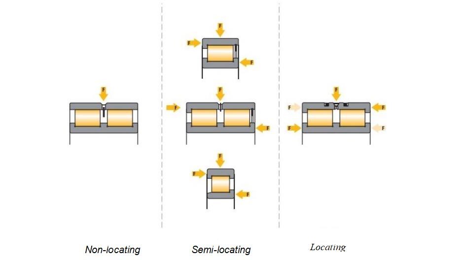
Full complement cylindrical roller bearings are designed without cages in order to have the maximum possible number of rolling elements. Therefore,they feature extremely high radial load carrying capacities and provide high rigidi- ty.However,due totheir kinematics,they have a lower speed ability as cylindrical roller bearings fitted with cages.
VEO full complement cylindrical roller bearings are available as single and double row designs as non-locating,semi-locating and locating bea- rings
Standard design variants
VEO full complement cylindrical roller bearings are available in several basic designs as stan- dard.
Single row full complement cylindrical roller bearings
VEO standard single row full complement roller bearings are semi-locating bearings.
NCF-V Design
NCF-V design bearings have two integral flanges on the inner ring and one integral flange on the outer ring.
They can support high radial forces but thrust forces in one direction and can therefore act as semi-locating bearings.
A retaining device (snap ring)in the flangeless side of the outer ring keeps the bearing assem- bly together during handling and transport.This retaining device must not be subjected to
thrust loads.
The maximum possible axial displacement of the bearing is provided in the product tables.
NJ23-VH design
The bearings series NJ23-VH is a separable full complement cylindrical roller bearing type.Its particular internal geometry allows for a self retaining roller complement.This allows for re- moving
the inner ring without having the rollers dropping out.
This bearing series is particularly suitable for low speed applications operating at high loads or shock loads
These semi-locating bearings can support high radial loads plus single direction acting thrust forces.
Double row full complement cylindrical roller bearings
VEO double row full complement roller bearings are being produced in various designs as standard including a full sealed variant.
All double row full complement bearings are non- separable and can be lubricated via a lubrication groove and lubrication holes in the outer ring (suffix W33).
NNCF50-V Design
This semi-locating bearing type has three integral flanges on the inner ring and one integral flange on the outer ring enabling the bearing to provide shaft guidance in one direction.
A retaining device(snap ring)in the flangeless side of the outer ring keeps the bearing assem- bly together during handling and transport.This retaining device must not be subjected to thrust loads.
NNC-V Design
NNC-V design full complement cylindrical roller bearings are locating bearings.They have three integral flanges on the inner ring and an axially split outer ring having two integrated flanges.
For manufacturing reasons the outer ring is axially split.The two outer ring halfes are being held together by circular clamping devices. These devices,however,must not be subjected to
thrust load.
NNCL-V Design
NNCL-V design full complement cylindrical roller bearings are double row non locating bearings. This design features three integral flanges on the inner ring and a plain outer ring without
flanges.
The assembled bearing is kept together for the purpose of mounting and transport via a reten- tion device attached to the outer ring.
Tolerances
VEO full complement cylindrical roller bearings are produced to tolerance class PN as standard. VEO bearings are also produced to closer toleran- ces,such as tolerance classes P6,P5 and P4 etc to customers order.
For obtaining detailed values on tolerances refer to the chapter Bearing data and Tolerances.
Internal radial clearance
VEO full complement cylindrical roller bearings are produced to normal internal clearance group (group CN)as standard.
VEO cylindrical roller bearings can be also produ- ced to other internal clearance groups to custo- mers order.
The clearance values correspond,as far as they are standardized,to the relevant international standards DIN620 part 4 and ISO 5753-1991.
The values of the internal clearance groups of single and double row VEO cylindrical roller bearings are listed in tables 1 and 2(page 291).
Non-standardized internal clearance
VEO full complement cylindrical roller bearings can also be produced with individually defined special internal clearances to customers order
This includes the possibility of producing bearings with a clearance restricted to a part of the full clearance range,i.e.C3H etc.
Minimum load
Rolling bearings require a sufficient minimum radial load to prevent excessive sliding friction. Particularly full complement cylindrical roller bearings requirea minimum radial load of more than
4%of the dynamic load rating Cr.
Equivalent dynamic bearing load
For non-locating type full complement cylindrical roller bearings and all other only radially loaded full complement cylindrical roller bearings apply:
P=F
In the case of single and double row full comple- mentcylindrical roller bearings accepting thrust loads,the following formula applies:
if  ,then:P=F
 ,then:P=X·F,+Y·F
|
Bearing series |
Calculation factors |
||
|
e |
X |
|
|
|
NCF-V(18) |
0,2 |
0.92 |
0,6 |
|
NCF-V(22,23,28,29,30) |
0,3 |
0,92 |
0,4 |
|
NJ23-VH |
0,3 |
0,92 |
0,4 |
|
NNCF50-V,NNC-V,NNCL-V |
0,15 |
0,92 |
0,53 |
VEO full of cylindrical rolling bearing internal gaps
|
Clearance group |
Bore diameter(mm) |
||||||||||||||
|
|
0 |
24 |
30 |
40 |
50 |
65 |
80 |
100 |
120 |
140 |
160 |
180 |
200 |
225 |
|
|
|
24 |
30 |
40 |
50 |
65 |
80 |
100 |
120 |
140 |
160 |
180 |
200 |
225 |
250 |
|
|
C1 |
min |
5 |
5 |
5 |
5 |
5 |
10 |
10 |
10 |
10 |
10 |
10 |
15 |
15 |
15 |
|
max |
15 |
15 |
15 |
18 |
20 |
25 |
30 |
30 |
35 |
35 |
40 |
45 |
50 |
50 |
|
|
C2 |
min |
0 |
0 |
5 |
5 |
10 |
10 |
15 |
15 |
15 |
20 |
25 |
35 |
45 |
45 |
|
max |
25 |
25 |
30 |
35 |
40 |
45 |
50 |
55 |
60 |
70 |
75 |
90 |
105 |
110 |
|
|
CN |
min |
20 |
20 |
25 |
30 |
40 |
40 |
50 |
50 |
60 |
70 |
75 |
90 |
105 |
110 |
|
max |
45 |
45 |
50 |
60 |
70 |
75 |
85 |
90 |
105 |
120 |
125 |
145 |
165 |
175 |
|
|
C3 |
min |
35 |
35 |
45 |
50 |
60 |
65 |
75 |
85 |
100 |
115 |
120 |
140 |
160 |
170 |
|
max |
60 |
60 |
70 |
80 |
90 |
100 |
110 |
125 |
145 |
165 |
170 |
195 |
220 |
235 |
|
|
C4 |
min |
50 |
50 |
60 |
70 |
80 |
90 |
105 |
125 |
145 |
165 |
170 |
195 |
220 |
235 |
|
max |
75 |
75 |
85 |
100 |
110 |
125 |
140 |
165 |
190 |
215 |
220 |
250 |
280 |
300 |
|
|
C5 |
min |
75 |
75 |
85 |
100 |
110 |
125 |
140 |
165 |
190 |
215 |
220 |
250 |
280 |
300 |
|
max |
100 |
100 |
110 |
130 |
140 |
160 |
175 |
205 |
235 |
265 |
270 |
305 |
340 |
365 |
|
|
Clearance grouo |
Bore diameter(mm) |
||||||||||||||
|
|
250 |
280 |
315 |
355 |
400 |
450 |
500 |
560 |
630 |
710 |
800 |
900 |
1000 |
1120 |
|
|
|
280 |
315 |
355 |
400 |
450 |
500 |
560 |
630 |
710 |
800 |
900 |
1000 |
1120 |
1250 |
|
|
C1 |
min |
20 |
20 |
20 |
25 |
25 |
25 |
25 |
30 |
30 |
35 |
35 |
35 |
50 |
230 |
|
max |
55 |
60 |
65 |
75 |
85 |
95 |
100 |
110 |
130 |
140 |
160 |
180 |
200 |
470 |
|
|
C2 |
min |
55 |
55 |
65 |
100 |
110 |
110 |
120 |
140 |
145 |
150 |
180 |
200 |
220 |
230 |
|
max |
125 |
130 |
145 |
190 |
210 |
220 |
240 |
260 |
285 |
310 |
350 |
390 |
430 |
470 |
|
|
CN |
min |
125 |
130 |
145 |
190 |
210 |
220 |
240 |
260 |
285 |
310 |
350 |
390 |
430 |
470 |
|
max |
195 |
205 |
225 |
280 |
310 |
330 |
360 |
380 |
425 |
470 |
520 |
580 |
640 |
710 |
|
|
C3 |
min |
190 |
200 |
225 |
280 |
310 |
330 |
360 |
380 |
425 |
470 |
520 |
580 |
640 |
710 |
|
max |
260 |
275 |
305 |
370 |
410 |
440 |
480 |
500 |
565 |
630 |
690 |
770 |
850 |
950 |
|
|
C4 |
min |
260 |
275 |
305 |
370 |
410 |
440 |
480 |
500 |
565 |
630 |
690 |
770 |
850 |
950 |
|
max |
330 |
350 |
385 |
460 |
510 |
550 |
600 |
620 |
705 |
790 |
860 |
960 |
1.060 |
1.190 |
|
|
C5 |
min |
330 |
350 |
385 |
460 |
510 |
550 |
600 |
620 |
705 |
790 |
860 |
960 |
1.060 |
1.510 |
|
max |
400 |
425 |
465 |
550 |
610 |
660 |
720 |
740 |
845 |
950 |
1.030 |
1.150 |
1.270 |
1.750 |
|
Dynamic axial load carrying capacity
Full complement cylindrical roller bearings are primarily designed to accommodate radial loads. Several designs are also suitable to accept thrust forces acting in one or both directions to a limi-
ted extend.
Thrust forces applied to cylindrical roller bea- rings generate sliding friction between the roller end faces and the guiding flanges.
Hence,an optimum lubrication is crucial.Fur- thermore,every thrust load creates a tilting mo- ment on the rollers
This requires an additional radial loading to ensu- re an effective function of the bearing.
The thrust forces appliedto the bearing must not exceed the following limits:
For single row bearings : Famax≤0,5-F
For double row bearings : Famax≤0,2-F
Equivalent static bearing load
For VEO single and double row full complement cylindrical roller bearings applies : P=F
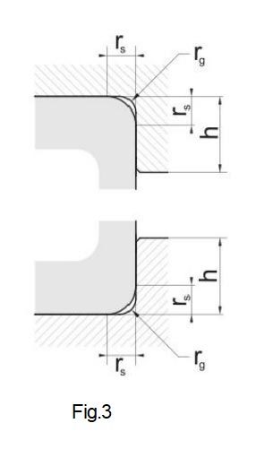
Abutment and fillet dimensions
The shoulders on adjacent machine parts must be designed in such a way that the required thrust support of the bearing rings is guaranteed.
The bearing rings must contact adjacent parts with their side faces only.
The bearing chamfers must not contact the shoul- der fillet radii of shaft or housing shoulders.
Therefore,the largest fillet radius (rg)must be kept smaller than the minimum chamfer on the bearing rings (rs)given in the product tables.
Recommendations for the dimensions of adjacent parts are given in DIN 5418.
Design of bearing seats as raceways
In applications with limited space it may bead- vantageous using a single or double row full com- plement cylindrical roller bearing in order to save on sectional height.
In thesecases,the rollers run directly on the sur- faces of housing.This contacting surface must be hardened and ground as forbearing raceways.
Typical types for these applications are RNN50-V series (double row)or RN-V series (single row).
The contacting surface on housing acting as ra- ceway must be produced to ISO tolerance field g6 and K6 respectively.
The diameters of the guiding flanges on housing must be in accordance with the respective shoul- der diameters (D₁),as given by the product ta- bles.
For detailed information on the design layout of raceways see chapter Design of bearing loca- tion.
|
rs rs min |
rg rgmax |
h |
|
Bearing Series |
||
|
18,22,29,30,48,49,50 |
||
|
0,3 |
0,3 |
1 |
|
0,3 |
0,5 |
1,6 |
|
0,6 |
0,6 |
1,6 |
|
1 |
1 |
2,3 |
|
1,1 |
1 |
3 |
|
1,5 |
1,5 |
3,5 |
|
2 |
2 |
4,4 |
|
2,1 |
2,1 |
2,1 |
|
3 |
2,5 |
6,2 |
|
4 |
3 |
73 |
|
5 |
4 |
9 |
FACTORY

Trade communication & visit


COMMON PROBLEM
GET A FREE QUOTE
RELATED PRODUCTS
Questions?
We are here to help.
Copyright ©
