


811,812
Category:
Cylindrical roller thrust bearings
Chat with us now for a quick response.
Keyword:
811,812
PRODUCT DETAILS
Technical characteristics
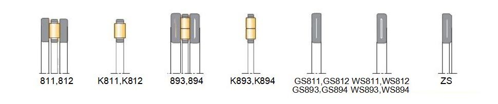
Cylindrical roller thrust Bearings series 811 and 812 are single direction acting separable axial bearings.
Cylindrical roller thrust bearings are also manu- factured in designs of double row cylindrical ro- ller corresponding to the series 893 and 894.
Cylindrical roller thrust bearingsare insensitive to shock loading and feature much higher load carrying capacity compared to thrust ball bea- rings.They accommodate very high axial loads but
no radial forces.They provide a very rigid bearing assembly for highthrust loading with less space requirement.
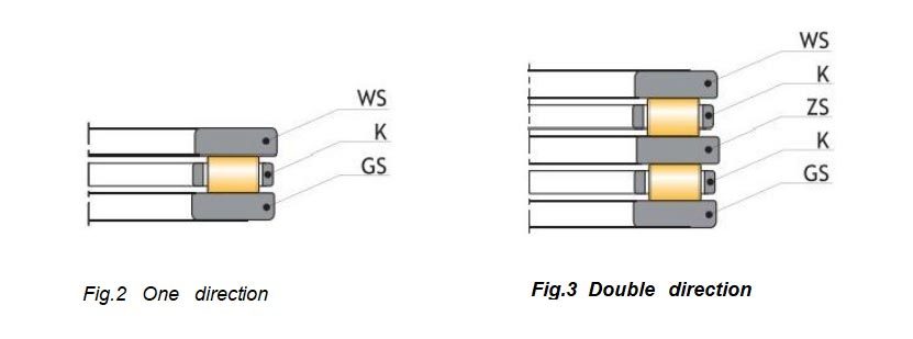
Cylindrical roller thrust bearings are of simple design,they consist of a shaft washer(WS),a housing washer(GS),and a cylindrical roller and cage thrust assembly (K).
With all cylindrical roller thrust bearings,increa- sed slidingfriction can occur on the end of the cylindrical rollers.
In order to minimise this negative effect,VEO cylindrical roller thrust bearings with wider sec- tional widths are produced using several short rollers in each cage pocket instead of using indi-
vidual longer rollers
Due to their specific kinematic behaviour,cylin- drical roller thrust bearings are only suitable for low speed applications only.
Furthermore,they require minimum axial loads for their optimum function.
Standard design variants
VEO cylindrical roller thrust bearings are produ - ced in single direction design only as standard. Double direction acting cylindrical roller thrust bearings are built using a
combination of com- ponents from single direction acting cylindrical roller thrust bearings together with intermediate washers ZS.
Such intermediate washers are part of VEO su- pplementary product range and are available on request.
For application designs with space restrictions the cylindrical roller and cagethrustassemblies may be used without washers providing the con- tact faces of adjacent machine parts
are ma- chined as bearing raceways,(e.g.hardened and ground,etc).
The components of cylindrical roller thrust bea- rings are frequently used either separately or in conjunction with other components in several applications (e.g.to build needle
roller thrust as- semblies)therefore,they are available as loose parts.
Misalignment
All cylindrical roller thrust bearing types do not allow any misalignment.
The contacting surfaces of both shaft and housing seats must be parallel.
Tolerances
VEO cylindrical roller thrust bearings are produ- ced to normal class tolerance (PN)as standard.
For applications of higher accuracy these bea- rings are produced to precision tolerance class (e.g.P6)on order request.
For detailed values of the tolerance classes see chapter Bearing data/Tolerances.
Cages
Small VEO cylindrical roller thrust bearings are fitted with shaft -centred polyamide cages as standard.
Polyamide cages are suitable for operating tem- peratures up to +120°℃(+248°F).
Large cylindrical roller thrust bearings are pro- ducedwith either solid brass cages (suffix M),or with solid steel cages,(suffix F).
Minimum load
All cylindrical roller thrust bearings require a cer- tain minimum axial load to ensure a satisfactory operating function.
To prevent excessive sliding friction,the mini- mum axial load applied should be greater than 5% of the axial bearing dynamic loadrating(Ca).
Where such a minimum axial load is not possible the load must be increased by effective measu- res,(i.e.preloading the bearing)using pressure washers or springs.
Equivalent dynamic bearing load
Cylindrical roller thrust bearings are pure axial bearings,they are not able to accommodate any radial loads,therefore:
P=F。
Equivalent static bearing load
For cylindrical roller thrust bearings :
P₀=F
Design of adjacent machine parts
When cylindrical roller and cage thrust assem- blies are used without washers adjacent machine parts must be designed and machined as bearing raceways (i.e.hardened and ground etc).
The maximum permissible axial runout of the ad- jacent surfaces acting as raceway must also meet the requirements of the respective washers.
For detailed information see chapter Design of bearing location.
The bore diameters of VEO cylindrical roller and cage thrust assemblies have tolerances according to ISO Tolerance field e11,whilst the tolerance of their outer diameters lies in the
tolerance field a13.
Cylindrical roller and cage thrust assemblies re- quire an effective guidance when operating at higher speeds.
To avoid excessive wear,at higher speeds,the guiding surfaces must be ground.
Bearing seats for cylindrical roller thrust bearings
For the design of cylindrical roller thrust bearing seats the followingof tolerance fields have pro- ven to be satisfactory in practice :
|
Centred on: |
Tolerances |
|
|
Shaft |
Housing |
|
|
Cylindrical roller and cage thrust assembly |
h8 |
H9 |
|
Shaft washer |
h6 |
|
|
Housing washer |
|
H7 |
Abutment and fillet dimensions
In the case of cylindrical roller thrust bearings,an effective support of the bearing washers over the total width of their raceways by adjacent machine parts is necessary.
The bearing washer must contact adjacent parts with their side face only.The fillet radii of bearing corners must not touch the shoulder fillet radii of the shaft or housing shoulders.
Therefore,the largest fillet radius(rg)must be smaller than the minimum fillet dimension of the bearing rings (rs)as listed in the following table 3 (page 361-362).
Supplementary designations
The product tables show the standardized bea- ring configurations updated on the edition of this catalogue.These standardized configurations co- rrespond to suffix or suffixes of each bearing.
In any case,VEO can offer,under requirement, alternative designs,comprising the ones showed in the following table or many others,whose mention exceeds the purpose of the present ca-
talogue,and can be found in specific technical publications of concrete applications or series of specific bearings.
Should you need a special design not existent in these pages,pleasecontactour Sales Department in VEO Bearings Europe.
|
Suffix |
Description |
|
TN |
Glass fiber reinforced polyamide cage |
|
M |
Solid brass cage |
|
P5 |
Increaseddimensional and running accuracy to /SO tolerance class 5 |
Abutment and fillet dimensions for cylindrical roller thrust bearings series 811 and 812[mm]
|
Shaft (mm) |
Bore reference nr. |
Bearing series |
|||||
|
811 |
812 |
||||||
|
D₃ |
D₄ |
b |
D₃ |
D₄ |
b |
||
|
min |
max |
min |
min |
max |
min |
||
|
15 |
02 |
25 |
18 |
0,3 |
|
|
|
|
17 |
03 |
27 |
20 |
0,3 |
|
|
|
|
20 |
04 |
32 |
23 |
0,3 |
|
|
|
|
25 |
05 |
39 |
28 |
0,6 |
|
|
|
|
30 |
06 |
44 |
33 |
0,6 |
49 |
33 |
0,6 |
|
35 |
07 |
49 |
38 |
0,6 |
56 |
41 |
1 |
|
40 |
08 |
56 |
44 |
0,6 |
63 |
45 |
1 |
|
45 |
09 |
61 |
49 |
0,6 |
68 |
50 |
1 |
|
50 |
10 |
66 |
54 |
0,6 |
73 |
55 |
1 |
|
55 |
11 |
73 |
60 |
0,6 |
84 |
61 |
1 |
|
60 |
12 |
80 |
65 |
1 |
89 |
66 |
1 |
|
65 |
13 |
85 |
70 |
1 |
94 |
71 |
1 |
|
70 |
14 |
90 |
75 |
1 |
99 |
76 |
1 |
|
75 |
15 |
95 |
80 |
1 |
104 |
81 |
1 |
|
80 |
16 |
100 |
85 |
1 |
109 |
86 |
1 |
|
85 |
17 |
105 |
90 |
1 |
117 |
93 |
1 |
|
90 |
18 |
114 |
96 |
1 |
127 |
98 |
1 |
|
100 |
20 |
129 |
106 |
1 |
140 |
110 |
1 |
|
110 |
22 |
139 |
116 |
1 |
150 |
120 |
1 |
|
120 |
24 |
149 |
126 |
1 |
160 |
130 |
1 |
|
130 |
26 |
162 |
138 |
1 |
179 |
141 |
1,5 |
|
140 |
28 |
172 |
148 |
1 |
189 |
151 |
1,5 |
|
150 |
30 |
182 |
158 |
1 |
204 |
161 |
1,5 |
|
160 |
32 |
192 |
168 |
1 |
214 |
171 |
1,5 |
|
170 |
34 |
207 |
178 |
1 |
227 |
183 |
1,5 |
|
180 |
36 |
217 |
188 |
1 |
237 |
193 |
1,5 |
|
190 |
38 |
230 |
200 |
1 |
256 |
204 |
2 |
|
200 |
40 |
240 |
210 |
1 |
266 |
214 |
2 |
|
220 |
44 |
260 |
230 |
1 |
286 |
234 |
2 |
|
240 |
48 |
288 |
252 |
1,5 |
322 |
258 |
2,1 |
|
260 |
52 |
308 |
272 |
1,5 |
342 |
278 |
2,1 |
|
280 |
56 |
337 |
293 |
1,5 |
362 |
298 |
2,1 |
|
300 |
60 |
365 |
315 |
2 |
398 |
322 |
2,5 |
|
320 |
64 |
385 |
335 |
2 |
418 |
342 |
2,5 |


|
Shaft (mm) |
Bore reference nr. |
Bearing series |
|||||
|
811 |
812 |
||||||
|
D₃ |
D₄ |
b |
D₃ |
D₄ |
b |
||
|
min |
max |
min |
min |
max |
min |
||
|
340 |
68 |
405 |
355 |
2 |
438 |
362 |
2,5 |
|
360 |
72 |
425 |
375 |
2 |
475 |
385 |
3 |
|
380 |
76 |
445 |
395 |
2 |
495 |
405 |
3 |
|
400 |
80 |
465 |
415 |
2 |
515 |
425 |
3 |
|
420 |
84 |
485 |
435 |
2 |
552 |
448 |
4 |
|
440 |
88 |
522 |
458 |
2,1 |
572 |
468 |
4 |
|
460 |
92 |
542 |
478 |
2,1 |
592 |
488 |
4 |
|
480 |
96 |
562 |
498 |
2,1 |
621 |
509 |
4 |
|
500 |
/500 |
582 |
518 |
2,1 |
641 |
529 |
4 |
|
530 |
/530 |
619 |
551 |
2,5 |
680 |
560 |
4 |
|
560 |
/560 |
649 |
581 |
2,5 |
715 |
595 |
4 |
|
600 |
/600 |
689 |
621 |
2,5 |
764 |
636 |
4 |
FACTORY

Trade communication & visit


COMMON PROBLEM
GET A FREE QUOTE
RELATED PRODUCTS
Questions?
We are here to help.
Copyright ©
